
single line diagram of power system cement pdf manufacturer Grasping strong production capability, advanced research strength and excellent service, Shanghai single line diagram of power system cement pdf supplier create the value and bring values to all of customers.
 WhatsApp)
1 day ago· The total assembled system weight with the B2 shall be 102 lb (46. Flow Control Valve. Single line diagram of AC power transmission system A typical single line diagram that represents the flow of energy in a given power system is shown below: Electric power is commonly (or usually) generated at 11 kV in generating stations in India and Europe.
May 26, 2020· Single line diagram (SLD) We usually depict the electrical distribution system by a graphic representation called a single line diagram (SLD). A single line can show all or part of a system. It is very versatile and comprehensive because it can depict very simple DC circuits, or a very complicated threephase system.
Jan 29, 2019· Concrete Electric Pole. There are two types of concrete poles: Poles; Poles; At present poles are used in 11 KV and 400/230 volt system to a large scale, apart from this, we also use PCC poles in 33KV Line. This type of poles is costlier than a wooden pole but cheaper than a steel pole.
of materials applicable to pv system none oneline diagram pv south transformer battery system pv301 solar power engineering 272 spring hollow lane montpelier, vt 05602 date: proj no. : scale: drawn by: issued for permitting gmp microgrid mwac pv 2 mwac battery project 11/08/2017 kl_mrs_1117 bpb 11/08/2017 129 ...
INDEX TERMS Clearances, Equipment''s Ratings, SLD (Single Line Diagram), Plan Layout, Section Elevation Layout, Earthing Grid, Earthing Grid Design, DSLP (Direct Stroke Lightning Protection), DSLP Design, OPGW Cable, Distribution Substation and Substation Design 1. INTRODUCTION The substations are important part of power system.
A distribution transformer or service transformer is a transformer that provides the final voltage transformation in the electric power distribution system, stepping down the voltage used in the distribution lines to the level used by the customer. The invention of a practical efficient transformer made AC power distribution feasible; a system using distribution transformers was demonstrated ...
fed by overhead line when a maximum HV earth resistance of 10 should be used. GENERAL EARTHING REQUIREMENTS The sections below detail the common earthing requirements that should be applied with the earthing layouts in Section HV ELECTRODE Bare copper cable and copper clad or galvanised rods are used as earth electrodes.
SINGLE LINE DIAGRAM A single line diagram is diagrammatic representation of power system in which the components are represented by their symbols and interconnection between them are shown by a straight line9eventhough the system is three phase ratings and the impedances of the components are also marked on the single line diagram.
power cable systems. This guide covers copper and aluminum conductors from No. 14 AWG though 1000 kcmil, insulated for operation from 600 volts though 35 kilovolts. Although this guide includes specific recommendations, it is impossible to cover all possible design, installation, and operating situations for every application.
The owner has to derive his supply from UmmBab Substation and run a new supply line to the New Cement Plant5, where a 33 / kV – incoming Transformer station has to be built. The layout, single line diagrams and the typical general arrangement drawings included in the Tender
120/240 VAC Single Split Phase Utility Power to the building / structure / house is fed from a Distribution Transformer that is either mounted on a utility pole (feeds through overhead lines) or on the ground on a concrete pad (Pad mounted, feeding through underground lines).
37 6. Diagram of user system for connection and MV switchgear 37 Diagram of the user installation 40 switchgear solutions 42 7. Power transformers 48 Main characteristics 46 Choice of transformers based on energy losses and efficiency 46 Efficiency requirements and classes for .
SINGLELINE DIAGRAMS Electrical Engineering Services 1 Ensuring Compliance An effective singleline diagram will clearly show how the main components of your electrical system are connected, including redundant equipment and available spares. It shows a correct power distribution path from the incoming power source to each downstream load —
Single Line Diagram of Power System Definition: Single line diagram is the representation of a power system using the simple symbol for each component. The single line diagram of a power system is the network which shows the main connections and arrangement of the system components along with their data (such as output rating, voltage, resistance and reactance, etc.).
Sep 01, 2018· For stepping up system voltage, we use stepup transformers and their associated protections and operations arrangements at generating station. We call this as generation substation. At the end of the transmission line, we have to step down the transmission voltage to a lower level for secondary transmission and or distribution we use step down transformers and their .
Single Line Diagram of Power System Definition its ...
Line diagram: a oneline diagram or singleline diagram is a simplified notation for representing an electrical system. The oneline diagram is similar to a block diagram except that electrical elements such as switches, circuit breakers, transformers, and capacitors are shown by standardized schematic symbols. Figure 3—Oneline diagram
Electric power systems are realtime energy delivery systems. Real time means that power is generated, transported, and supplied the moment you turn on the light switch. Electric power systems are not storage systems like water systems and gas systems. Instead, generators produce the energy as the demand calls for it. Figure 11 shows the basic ...
68. 31 6011 Rev. B – Substation Standards Typical Power Circuit Breaker Wiring Diagram (Sh 1 of 3) 69. 31 6012 Rev. B – Substation Standards Typical Power Circuit Breaker Wiring Diagram (Sh 2 of 3) 70. 31 6013 Rev. B – Substation Standards Typical Power Circuit Breaker Wiring Diagram .

United States Department of Agriculture Rural Utilities Service RUS Bulletin 1724E300 Issued June 2001 Design Guide for Rural Substations
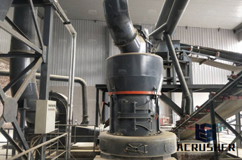
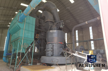
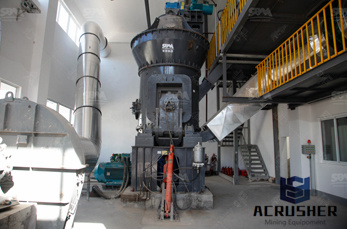
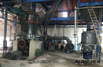
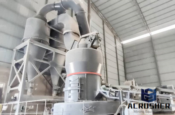
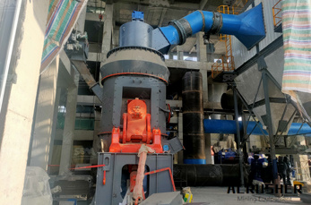
cement plant one line diagram greenrevolutionorgin cement factory electrical single line diagram pdf,cement plant one line diagram, at their Cement Plant site Cement manufacturing components of a cement Cement manufacturing: components of a cement plant This page and the linked pages below summarize the cement manufacturing process.
Introduction to Power Systems Class Notes Chapter 4 Introduction To Symmetrical Components ∗ Kirtley Jr. 1 Introduction Installment 3 of these notes dealt primarily with networks that are balanced, in which the three voltages (and three currents) are identical but for .
power system is balanced 3phase .However, due to sudden external or internal changes in the system, this condition is disrupted. When the insulation of the system fails at one or more points or a conducting object comes into contact with a live point, a short circuit or a fault occurs. CAUSES OF POWER SYSTEM FAULTS
in Russia between Elektrostal and the power station at Ekibastusz, this was a threephase alternating current line at 1200 kV (Power line EkibastuzKokshetau). In 1999, in Japan the first power line designed for 1000 kV with 2 circuits were built, the KitaIwaki Power line. In 2003 the
WhatsApp)